New Project: Hydraulic Tracer
Hello!
Over the last few days, I've been developing a new project idea. The idea came out of an application where I need to produce a cam for a cam-follower setup. Currently, I don't know what the shape of that cam is going to be, but I would like to be able to have a method for producing cams that would work for nearly any shape of cam.
I don't have CNC control on my lathe or milling machine, nor do I currently have a way to synchronize a rotary table with the movement of a linear axis. So, the last method apparently available to me is the 'drill and file method', wherein a disk (in the case of a disk cam) has holes drilled at the periphery of the intended cam shape. The disk is then cut so as to remove the disk material excess to the cam shape, and then filed to finish. There might then be some grinding, but that's at least how the rough shape is obtained.
I would love for the fabrication of a cam out of metal to be as easy as the fabrication of a cam out of wood; just cut out the rough shape by hand with a saw which gives you sensitivity to the shape you're forming (a coping saw), and then file and sand until you've reached your intended shape.
Just think about how great it would be to have a way to shape metal with the same sort of free-hand creativity that a carpenter might use in shaping something out of wood. We can't really have the same type of organic control over our forming of metals as we do for wood...or clay...which is due to the significantly higher forces required in the machining of metal parts.
Well, what i'm looking for then is some type of force amplifier. It turns out that something very much like this already exists, and was used quite extensively before the age of CNC machinery to produce complex and curved profiles on metal parts. It's called 'the hydraulic tracer'.
Basically a hydraulic tracer is a system wherein a stylus, which actuates a set of valves, follows the edge of a 'pattern' guide, and is moved by the hydraulic rams which it's valves are controlling. More or less, this is a hydraulic 'line-follower'.
Take the case of a single-axis tracer; one ram is moving one stylus head along one axis. As the ram slowly moves, the stylus eventually makes contact with an edge of the pattern. Shortly after the stylus makes contact with the edge of the pattern, the pattern pushes on the stylus and causes it to shift, which in turn shifts the valves connected to the stylus so as to stop the movement of the hydraulic ram.
If this system is operating on one axis, and a slow constant movement is applied to the pattern in a perpendicular axis (assume that the edge of the pattern which was found by the stylus, extends into this new 'perpendicular axis'), then the system will cause the stylus to follow the edge of the pattern. Attach a machine tool to the movements of the pattern and stylus head, and the machine tool will then follow the same path as the stylus, which is the path prescribed by the shape of the pattern. Voila!
This system was used on all sort of equipment; I'm under the impression that it was first used on lathes, in order to copy a 2D pattern onto a round part, so as to produce a revolved version of that 2D pattern. I also know that these systems were used on milling machines for both linear and rotary axis. Sometimes the control for multiple axis is performed with a single multi-directional stylus. Other times, it can be more useful to break the three control systems into three separate stylus and ram system, which is shown in the last photograph below. The last photograph below is particularly interesting because the hydraulic tracer systems used in the application shown, are controlling hydraulic motors rather than rams, and these motors are moving a linear axis as well as a dividing head (a rotary axis).
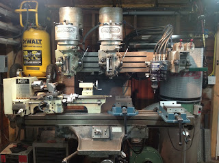
[ A 'T-ram' Bridgeport with an X and Y 'True-Trace' tracer system. Two copies of a pattern can be made with the two milling heads mounted on the T-ram. ]

[ Hydraulic tracer systems on a linear axis and rotary axis, for machining turbine components. ]

So, I'd like to have a better understanding of the design of the valve system in the stylus head. As an exercise, I'd also like to design my own valve system. To that end, I've begun investigating OpenFOAM, which is an open-source computational fluid-dynamics software package. Once I've developed a design that performs well, I will fabricate the valve, purchase a hydraulic pump and a ram suitable for the Y axis of my lathe (or, possibly the X or Z axis of my milling machine), and begin using this tracer system to replicate hand-made wooden parts (such as hand-made cams) out of metal. The rotary table rotation will be driven by a gearmotor, and the tracer system will respond to the shape of the cam pattern in the radial direction. The cam pattern will likely be mounted coaxially with the metal cam blank, although the only actual requirements are that it be the same size and be at the same angle about it's central axis as the blank at all times.
If I make a second one, I can have an X-Y stylus, which I can then control by hand so as to produce shapes quasi-free-handedly on my lathe or milling machine. I suppose servo-motors could be connected to the stylus so that my computer can have in on the fun too.
Over the last few days, I've been developing a new project idea. The idea came out of an application where I need to produce a cam for a cam-follower setup. Currently, I don't know what the shape of that cam is going to be, but I would like to be able to have a method for producing cams that would work for nearly any shape of cam.
I don't have CNC control on my lathe or milling machine, nor do I currently have a way to synchronize a rotary table with the movement of a linear axis. So, the last method apparently available to me is the 'drill and file method', wherein a disk (in the case of a disk cam) has holes drilled at the periphery of the intended cam shape. The disk is then cut so as to remove the disk material excess to the cam shape, and then filed to finish. There might then be some grinding, but that's at least how the rough shape is obtained.
I would love for the fabrication of a cam out of metal to be as easy as the fabrication of a cam out of wood; just cut out the rough shape by hand with a saw which gives you sensitivity to the shape you're forming (a coping saw), and then file and sand until you've reached your intended shape.
Just think about how great it would be to have a way to shape metal with the same sort of free-hand creativity that a carpenter might use in shaping something out of wood. We can't really have the same type of organic control over our forming of metals as we do for wood...or clay...which is due to the significantly higher forces required in the machining of metal parts.
Well, what i'm looking for then is some type of force amplifier. It turns out that something very much like this already exists, and was used quite extensively before the age of CNC machinery to produce complex and curved profiles on metal parts. It's called 'the hydraulic tracer'.
Basically a hydraulic tracer is a system wherein a stylus, which actuates a set of valves, follows the edge of a 'pattern' guide, and is moved by the hydraulic rams which it's valves are controlling. More or less, this is a hydraulic 'line-follower'.
Take the case of a single-axis tracer; one ram is moving one stylus head along one axis. As the ram slowly moves, the stylus eventually makes contact with an edge of the pattern. Shortly after the stylus makes contact with the edge of the pattern, the pattern pushes on the stylus and causes it to shift, which in turn shifts the valves connected to the stylus so as to stop the movement of the hydraulic ram.
If this system is operating on one axis, and a slow constant movement is applied to the pattern in a perpendicular axis (assume that the edge of the pattern which was found by the stylus, extends into this new 'perpendicular axis'), then the system will cause the stylus to follow the edge of the pattern. Attach a machine tool to the movements of the pattern and stylus head, and the machine tool will then follow the same path as the stylus, which is the path prescribed by the shape of the pattern. Voila!
This system was used on all sort of equipment; I'm under the impression that it was first used on lathes, in order to copy a 2D pattern onto a round part, so as to produce a revolved version of that 2D pattern. I also know that these systems were used on milling machines for both linear and rotary axis. Sometimes the control for multiple axis is performed with a single multi-directional stylus. Other times, it can be more useful to break the three control systems into three separate stylus and ram system, which is shown in the last photograph below. The last photograph below is particularly interesting because the hydraulic tracer systems used in the application shown, are controlling hydraulic motors rather than rams, and these motors are moving a linear axis as well as a dividing head (a rotary axis).
[ A 'T-ram' Bridgeport with an X and Y 'True-Trace' tracer system. Two copies of a pattern can be made with the two milling heads mounted on the T-ram. ]

[ Another picture of the True-Trace system on a two-headed 'T-ram' Bridgeport ]

[ Hydraulic tracer systems on a linear axis and rotary axis, for machining turbine components. ]

So, I'd like to have a better understanding of the design of the valve system in the stylus head. As an exercise, I'd also like to design my own valve system. To that end, I've begun investigating OpenFOAM, which is an open-source computational fluid-dynamics software package. Once I've developed a design that performs well, I will fabricate the valve, purchase a hydraulic pump and a ram suitable for the Y axis of my lathe (or, possibly the X or Z axis of my milling machine), and begin using this tracer system to replicate hand-made wooden parts (such as hand-made cams) out of metal. The rotary table rotation will be driven by a gearmotor, and the tracer system will respond to the shape of the cam pattern in the radial direction. The cam pattern will likely be mounted coaxially with the metal cam blank, although the only actual requirements are that it be the same size and be at the same angle about it's central axis as the blank at all times.
If I make a second one, I can have an X-Y stylus, which I can then control by hand so as to produce shapes quasi-free-handedly on my lathe or milling machine. I suppose servo-motors could be connected to the stylus so that my computer can have in on the fun too.

Comments
Post a Comment