Five or six years ago, I made a deal with the owner of the building where I have my shop, for an old non-functioning forklift that had been sitting outside under a rotten tarp for many years. If I could make it run, it was mine.
And so I did. At first it ran only on three of the four cylinders of it's Continental flathead engine. Because of how much smoke it made, you could basically only use it on windy days; otherwise the cloud of smoke surrounding you would soon prevent you from seeing what you were doing. Not to mention, it leaked a watery-oil mixture all over the parking lot wherever it went (you can see the beginnings of a water/oil trail in the photos below). But, it was useful for getting machinery up and down from loading-dock height, and I used it like that for a couple years.
So, just before the pandemic hit, I had decided to do a complete nut-and-bolt rebuild of the forklift.
This forklift is a 1930's Clark Carloader; apparently the first model of "short-coupled" hydraulic forklift that Clark ever produced (photo courtesy Clark:
https://clarkmheu.com/en/company/history):
I was able to find a fairly detailed manual for it, produced by the War Department:
My favorite part of the technical manual, is a section called, "Demolition to Prevent Enemy Use".
Unfortunately I didn't take many pictures during the disassembly process.
Andrew Birkel helped with disassembly, and a great deal of the cleaning, priming, and painting of the individual parts.
I do have pictures of the chassis, once everything else had been removed, and the chassis was being painted. Once the original finish was entirely sanded off and wire-wheeled, the entire chassis was scrubbed with acetone, and left to dry. One coat of self-etching primer was applied to the entire chassis, followed by a coat of filler primer, which was then followed by six coats of gloss black enamel paint.
Almost all of the paints used on this project were alkyd enamel paints, sourced from Gillespie Coatings Inc., largely through a military-vehicle restoration specialty site, armyjeepparts.com. Gillespie Coatings produces very durable coatings and paints for industrial applications, and as far as I understand, has a history of producing paints and coatings for the US Military. Links:
The most unusual thing I found during the disassembly, was the governor used on the engine. I'm accustomed to seeing mechanical engine-driven governors, that are usually linked to the engine's front gear-train, or occasionally aftermarket mechanical governors that are belt-driven and connected to the engine's fan belt route. This engine, though, had what's apparently called a 'velocity governor'. A velocity governor acquires it's engine-rpm feedback signal from the vacuum pressure that is being developed in the intake manifold, and so it's mounted between the carburetor and intake manifold. More vacuum pressure means the engine is spinning faster, and so the velocity governor closes down the throttle. Less vacuum pressure means the engine is spinning slower, and so the governor opens up the throttle. This is a very interesting system, and makes for a very compact method of governing. Unfortunately, the velocity governor was entirely rusted and corroded, to the point of extreme decay of most of the internal parts.
The rest of the original 4-cylinder continental engine was also in very rough shape. It turned out that a critter had been living in the fourth cylinder, and the debris that had been packed into that cylinder by the critter, had caused the walls of the cylinder bore to become deeply pitted. The cylinders would need boring and sleeving, if the original engine was going to be saved.
The cause of the constant oil leakage all over the parking lot from the engine, was overflow of an oil/water mixture from the oil overflow tube. Engine coolant was leaking into the engine oil, whenever the engine ran, causing the engine oil level to rise and overflow. At one point, while running the engine with the radiator cap removed, it was discovered that exhaust would bubble out of the coolant water and escape out of the top of the radiator.
The original engine was a Continental F-162, with some special machining done on the front of the engine block to accommodate an extra idler gear, used to connect an engine-mounted hydraulic pump to the crankshaft gear.
Continental F-162's and F-163's are fairly ubiquitous industrial 4-cylinder engines. They were used in all sorts of applications; forklifts, tractors, combines, generators, welder-generators, water pumps, dedicated-pto power units, etc.. The engines themselves are easy to find, and replacement parts are still cheap and readily available. The F-163 has some minor design advancements over the F-162, but 99% of the parts are compatible between the two models.
So, I found a generator for sale on craigslist in Vermont with a continental F-163 in good working order; and Emily and I made the trip into a weekend getaway.
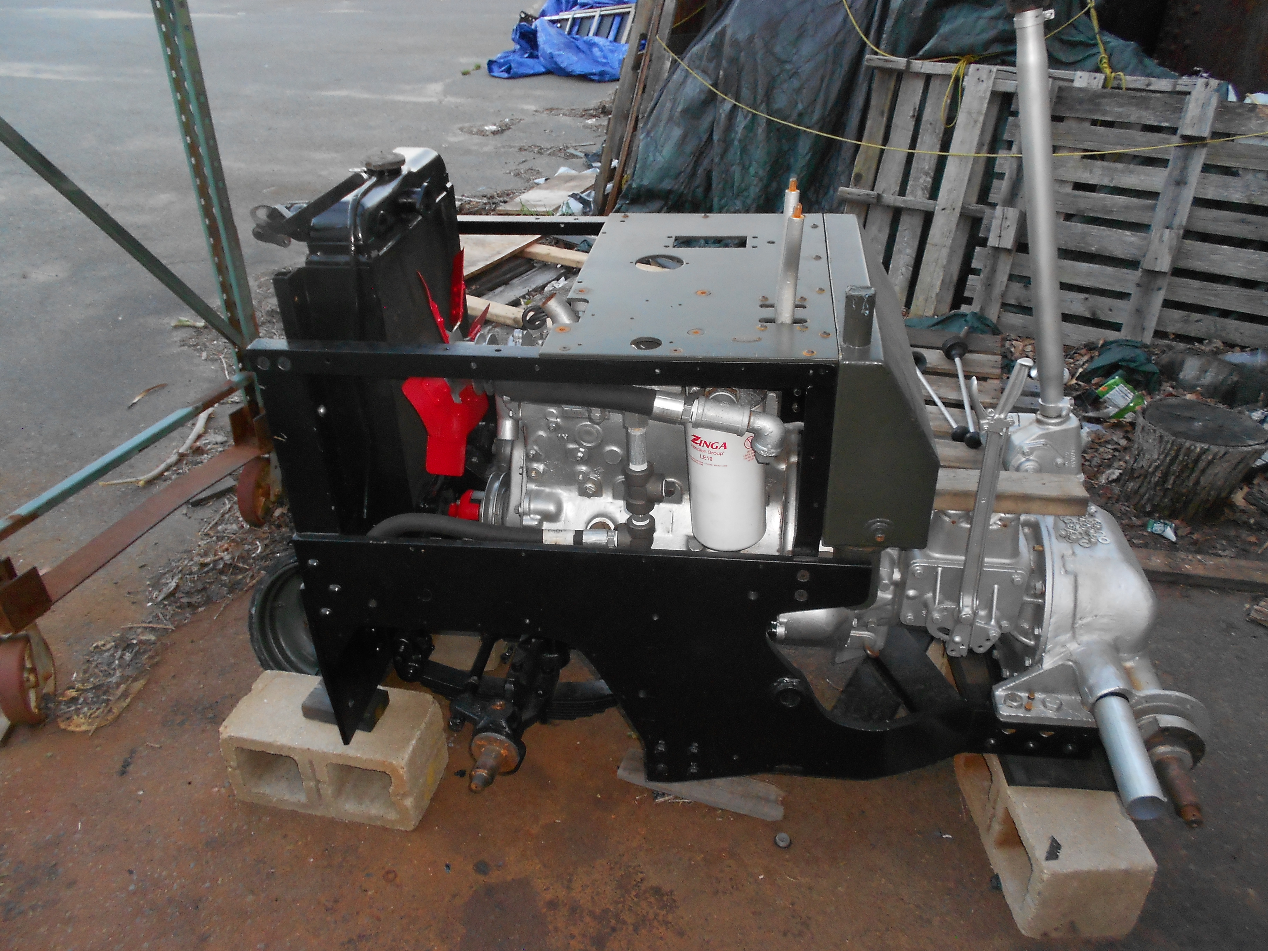
Here's the new generator engine mounted to the rebuilt transmission (all new bearings, seals, gaskets), in the chassis:


Because this was a generator engine, and not a forklift engine, a new mounting scheme had to be arranged to drive a hydraulic pump. As seen in the above pictures, a gear pump with a standard SAE type flange, was mounted through a hole cut in the chassis cross-bar in front of the engine. A large Lovejoy coupling was adapted to attach to the front of the crankshaft pulley, which drives the hydraulic pump. Notice that the elbow on the left side of the gear pump which is the suction line, is a special design with a 1/8" NPT plug at the corner of the elbow. This plug is used to verify that oil is getting all the way up to the pump, before running it.
The original hydraulic pump in the forklift was a vane type pump made by Vickers. Vane pumps are fairly tolerant of small particulate debris in the hydraulic oil. So, the original hydraulic circuit did not include any filtering of the hydraulic fluid. The original hydraulic pump, unfortunately, required rotation in the wrong direction, with respect to the direction of rotation of the crankshaft that the pump would see in the new mounting position. For that reason, it was replaced with an off-the-shelf gear pump from
Surplus Center. Unlike vane pumps, gear pumps are not very tolerant of small particles in the hydraulic fluid, and manufacturers of gear pumps typically advise that the hydraulic oil passing through the pump, is filtered to some level in the range of 10-30 microns. A large filter was therefore installed on the return line from the control valve block (white cannister with the 'Zinga' branding on it in the image below). This is a thread-on cartridge filter, which interfaces much like engine oil filter on most cars, except that it's much bigger.

The bulkhead fitting on the gas tank was originally an 1/8" npt fitting. I wanted to install a combination sediment-bowl shutoff valve, and I couldn't really find one for 1/8" npt. So, I fabricated a new bulkhead fitting for 3/8" npt, and installed it after removing the original bulkhead fitting, using silver-solder.
Important note here: before any torch related work the gas tank was washed thoroughly, inside and out, with soap and water several times before applying a torch to any part of it. Further, an initial flame test was done in an outdoor area where I waved the torch past the various openings of the gas tank, to verify that there were absolutely no flammable residues still present in the tank.


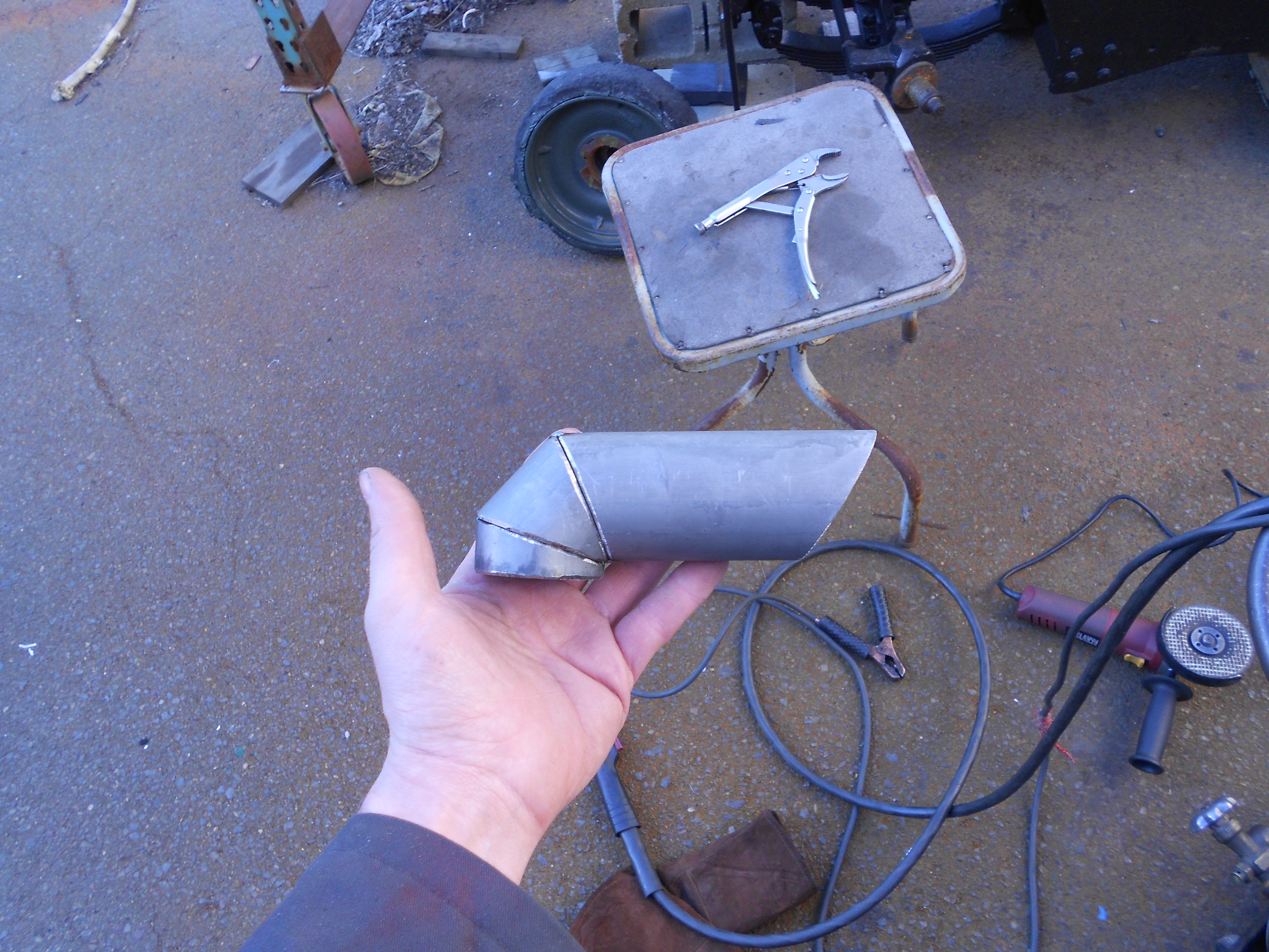
One of the fabrication techniques that I've been getting a lot more practice on, is a method of constructing turns and bends by joining sections of tube that are cut at an angle. This was necesssary in the fabricaton of new muffler piping, as well as some very special shapes of radiator fittings on this forklift.
You should never weld steel that is galvanized, the zinc fumes are very toxic. What I had for raw material for the exhaust piping construction was 2" EMT (electrical conduit), and to remove the zinc, I soaked the pieces of EMT in vinegar. Normal household grade cooking vinegar would work for this, but wanting to speed things up, I used "cleaning vinegar", which is just very concentrated vinegar.
The body of the muffler is from the generator that this engine came in, and the flange at the end of the piping was machined from a piece of 1/4" steel plate.
After grinding the welds and painting, this exhaust system is looking pretty good. High-temperature primer first:
Then high-temperature paint:
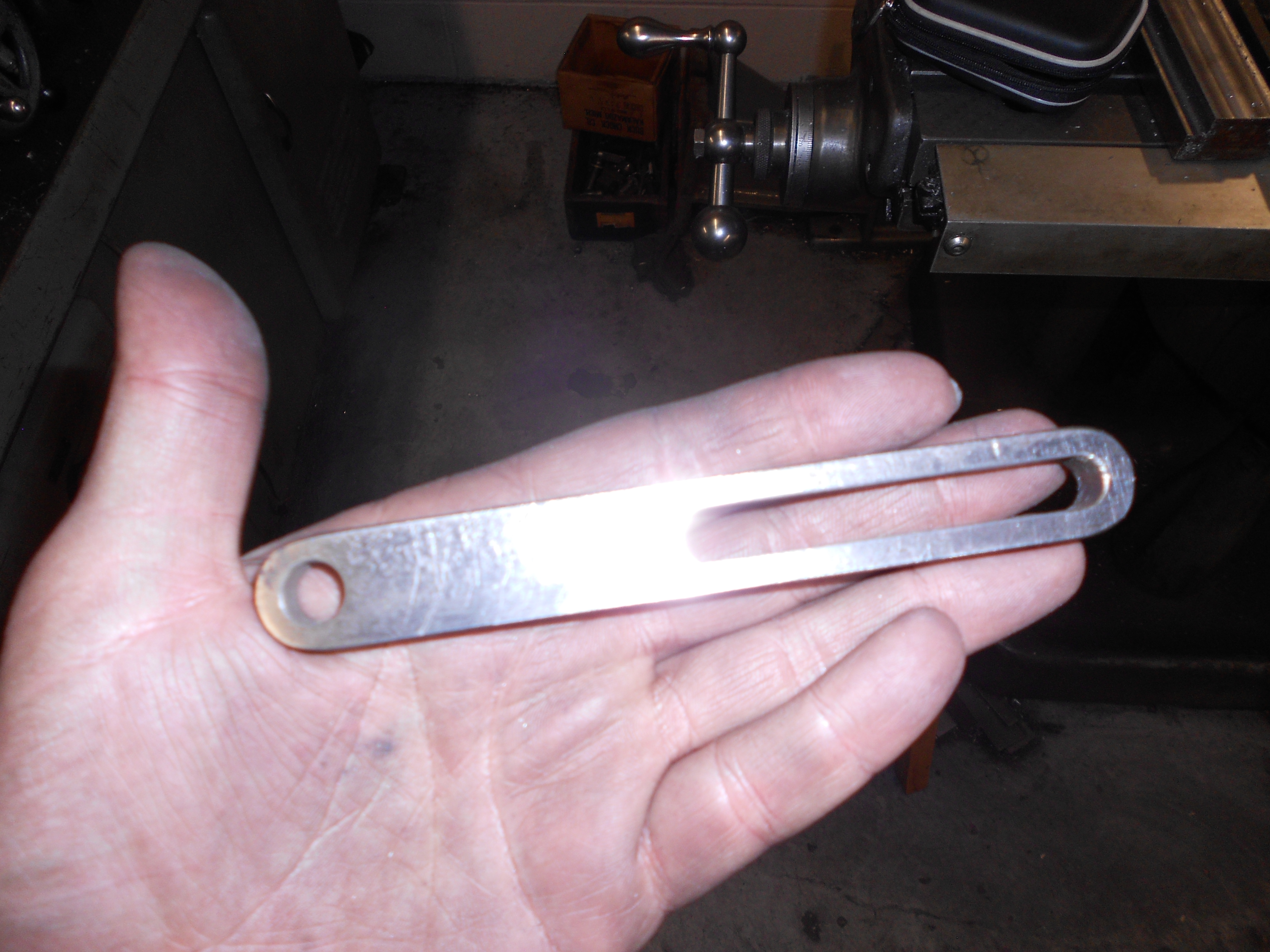
A great deal of custom bracketry was fabricated for this project, because many of the components, including the engine, were new, and mounted differently than what originally came in the forklift. Here are some details of custom brackets fabricated for mounting a modern alternator to the engine:
Alternator pivot bracket, after fabrication and paint:
Machining the tensioning link for the alternator:
Nearly finished tensioning link:
Extra material at the left end was cut off on the bandsaw, corners rounded on the belt sander, and the entire piece sanded:
Fit-check of the tensioning link; looks good:
Finally, prime and paint:
There's a lot more to this story, including rebuild of the hydraulic cylinders, which I will include in a 'Part 2' post soon.
Thanks for reading!


Comments
Post a Comment