July 2019 Update; Resurrecting the Blog!
Hello!
Many years have passed since I last made a post; many things have happened, and many developments have been made since 2013. The vast majority of machinery I've acquired, was acquired since 2013; the period of rapid machinery acquisition is itself an entire story involving getting access to a 7,500 square foot shop facility in Waltham as well as a small industrial space in Lynn MA, designing and building portable lifting and rigging equipment, many many Uhaul trailer rentals, etc. A LOT has happened since my last post in 2013. I will work at documenting that period of time.
Current project: Automation of ram-type turret for 16" South Bend Lathe:
Now that gearcutting is extremely easy to do, I'm trying to work at reducing the burden of the next most machining-intensive part of the gear-making process: machining the blank. At the moment, making a gear blank involves cutting a slice off of a bar of stock or a section of flat steel plate, drilling the piece at it's approximate center in order to hold it on a mandrel, installing the piece on either a mandrel that I have also turned for that specific purpose, or an expanding or tapered mandrel that I already have, and then turning both faces and the outside diameter. This is a fairly tedious and uninteresting process, and so I am trying to put together some automatic means of making gear blanks. I'd like to be able to set up a turret lathe to do the work; a turret lathe or CNC lathe with through-spindle capacity somewhere in the range of 4 to 7 inches would be ideal for making blanks that my Fellows machines can handle, but at the moment that sort of machine is far out of my budget.
Behold! The aftermarket lathe turret:
Amongst other things, Enco made aftermarket lathe turrets. Basically, these are ram-type turrets that are universal in construction, that the end-user (or possibly the factory) custom fits to a particular machine. I bought this turret from a guy in Staten Island for $75. It was originally fitted to a Colchester 15" lathe, but I will be re-machining the underside surface in order to fit it to a 16" South Bend lathe.
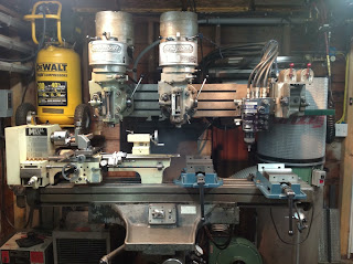
The 16" South Bend lathe:
This is the lathe that the turret will be fitted to. There is also a 10" South Bend lathe in the shop, which is used much more often that this one, and so semi-dedicating this lathe to gear-blank fabrication, makes sense.
Automation of the Turret:
The point in turret-izing the turning and boring operations of gear-blank making, is to reduce as much as possible, the effort needed by the operating to make a gear blank. A conventional turret lathe looks something like this:
The signature feature of the turret lathe is the multi-sided turret, which is in place of the tailstock on a conventional engine lathe. The turret is a six or eight-sided block which rotates on a vertical axis, and can be locked into place with any of it's faces facing the headstock. So, the operator can mount six or eight different tailstock tools (drills, reamers, counter-bores, end-mounted turning tools, die-heads, collapsing-tap arrangements, etc.), and rapidly change between tools without having to re-calibrate tool settings or positions. The turret lathe was en extraordinary leap forward in the mass-production of turned parts, and is often credited as being the most important technology which facilitated the massive war-related production that enabled the Allied victory in World War II.
Turret lathes have all sorts of fancy features like power-feed on the turret, automatic bar-feeding (stock-feeding through the spindle), and automatic turret indexing. My Enco turret does have automatic turret indexing (the turret indexes when the operator cranks the handwheel backwards, into the end-of-travel), but does not have any of the other fancy features. But, now that I can make basically any gear that I can possibly need, I decided to add a two-speed power feed to the turret.
Two-speed geared power-feed for the Enco turret, the plan:
I did some very crude CAD modelling of the power-feed gearbox; it's crude because it's exclusively for the purpose of figuring out gear center positions and tooth counts. Generally for my own personal projects, I don't put an excruciating level of detail into CAD models. Because I don't need to hand the design off to another engineer, or make drawings, or communicate with vendors, I will only put as much detail into CAD models as is absolutely necessary for my own calculations of dimensions and part features, etc.. Anything that I can reliably calculate "on-the-fly", I'll leave out of the model. So, you'll notice that the gears don't have teeth, and no bushings or bearings are shown. For each gear, the sketch for that part contains the pitch-diameter circle as a construction line, and an outside-diameter circle for defining the edge of the boss/extrusion. In the assembly, the gears are mated by their pitch circles.
Here are the specs for the gears in the model:
A: 36 teeth, 12DP, 14.5PA, 3.167" OD, 0.750" thick
B: 12 teeth, 12DP, 14.5PA, 1.167" OD, 0.750" thick
C: 24 teeth, 16DP, 14.5PA, 1.625" OD, 0.750" thick
D: 12 teeth, 16DP, 14.5PA, 0.875" OD, 1.5" thick (this gear will slide axially, so it is 2x long)
E: 24 teeth, 20DP, 14.5PA, 1.300" OD, 0.625" thick
F: 60 teeth, 20DP, 14.5PA, 3.100" OD, 0.625" thick
G: 12 teeth, 20DP, 14.5PA, 0.700" OD, 0.625" thick
H: 24 teeth, 20DP, 14.5PA, 1.300" OD, 0.625" thick
I: 12 teeth, 20DP, 14.5PA, 0.700" OD, 0.625" thick
J: 24 teeth, 20DP, 14.5PA, 1.300" OD, 0.625" thick
K: 12 teeth, 20DP, 14.5PA, 0.700" OD, 0.625" thick
L: 24 teeth, 20DP, 14.5PA, 1.300" OD, 0.625" thick
M: 12 teeth, 20DP, 14.5PA, 0.700" OD, 0.750" thick
N: 60 teeth, 20DP, 14.5PA, 3.100" OD, 0.750" thick
This gearbox will fit on the front side of the saddle, to the left of the handwheel stem/shaft:
This gearbox has two geared speeds; a "slow" ratio (moves the turret roughly 1.2 inch/min) for advancement of the tool into the workpiece, and a very fast speed ( ~100 inch/min) for the backwards-return of the turret and turret indexing. Speed-switching will be done via dog-clutch, which I will actuate either with a hand-lever, or with a solenoid. The dog-clutch will be located between gears 'E' and 'N', and so the design may end up such that the shaft that gear 'D' sits on, slides. For that reason, I've made gear 'D' twice as long as the gear that it mates with, to accommodate axial sliding action.
This will be powered by a Bodine 1/20th hp motor (shown below), which will be mounted to the opposite side of the saddle; a shaft will run through the saddle (under the ram mechanisms) to connect the gearmotor to the power feed gearbox. I also have a DC version of this gearmotor which I might use instead, so that I can do electronic variable speed control.
Cutting the gears!
I have already begun cutting the gears for this gearbox on a Fellows 7a gear shaper. I spent a lot of time augmenting one of my Fellows 7a machines so that it would be ready for universal usage, without the need for a lot of special fixturing or setup each time I need to make a gear. This augmentation involved fabricating an adapter plate to attach a 3-jaw chuck (Bison 8" Set-Tru chuck) to the work-holding table, installing 3 inches of riser block to the top-half of the machine to compensate for the 3-inch tall chuck, making shaft extensions for the various drive shafts within the machine to connect shafts that were spaced apart by the inclusion of the 3-inch riser block, etc.. The "Set-Tru" system on the Bison chuck is a system of four radially-located set-screws that allow you to accurately center the chuck when you install it. I copied this design into my adapter plate; the adapter plate also has radial set-screws for accurate centering.
This Fellows machine could definitely use a paint job, but mechanically it's in good shape:
To date, I've fabricated gears 'A', 'B', 'C', 'D', and 'N', (shown below). Gears 'B' and 'C' are part of a cluster gear. If I was hobbing these gears, or milling them with form tools, all of my cluster gears would need to be two-piece gears; I would make each gear and then press them together. But, the Fellows process has a very interesting capability; because the gearcutting process is a reciprocating profile-shaping process, I can use the machine to cut a gear-tooth profile up to a stop; no exit clearance is needed. Therefore, gears 'B' and 'C' were cut into one single piece of metal.
Where did all of this machinery come from?
Back in December/January, I found a number of gear shaper machines for sale out in Springfield MA. There were four Fellows 7a gear shapers, one Fellows #6 shaper, a couple Barber Colman No. 3 gear hobbers, a gigantic Gleason bevel-gear planer, and a couple Illitron gear inspection machines for sale, for prices that were basically scrap value or below. So, I acquired all four of the Fellows #7a machines, the Fellows #6 machine, one of the Barber Colman No. 3 hobbers, and two Illitron gear-inspection machines. Before this acquisition, I had already obtained a Barber Colman No.3 gear hobber, a Gauthier W1 gear hobber, and a Hercules 8-inch gear hobber; I will do a post with greater detail on these machines and their features, in the near future.
My rigging and heavy-haulage hobby started several years ago when I purchased a small Pratt & Whitney turret lathe from a guy who was using it to make designer bicycle parts. I enlisted the help of a long-time friend, and we were able to move that machine (roughly 800 lbs) using two people, a johnson bar, and a small Uhaul trailer pulled by a jeep wrangler.
The next machine acquisition was a 14-inch F.E.Reed engine lathe from the early 1900's. This was the first of the 2000lb+ class machines that I acquired, and in order to move it I constructed a portable gantry crane. This gantry crane is capable of lifting 6000lbs, disassembles into a modest flat pack, and is fully assemble-able and disassemble-able by two people in about ten minutes (I will do a post about that build at some point).
From there, the rigging hobby and machinery acquisition really took off. With the help of close friends and my partner Emily, I've moved somewhere around 43 machines. Most of these are machines that I salvaged or acquired, some of them were my father's machinery when he moved his shop across town, and some of them were for another close friend who I helped set up a small machine shop for restoration work in Lynn, MA. The rigging hobby has taken us to some extremely interesting places, allowed us access to a lot of extremely interesting industrial history, and gained us great friends in great places.
After de-constructing a 1902 American Sawmill Machinery Co. sawmill in Riegelsville, PA, and hauling it to family land in central Massachusetts, Emily set up a youtube channel to chronicle our machinery-related adventures. You can find the youtube channel here:
"Reeve - Giroux Youtube Channel"
If the link stops working, just search "Reeve-Giroux" in youtube and click on the one that looks like this:

Many years have passed since I last made a post; many things have happened, and many developments have been made since 2013. The vast majority of machinery I've acquired, was acquired since 2013; the period of rapid machinery acquisition is itself an entire story involving getting access to a 7,500 square foot shop facility in Waltham as well as a small industrial space in Lynn MA, designing and building portable lifting and rigging equipment, many many Uhaul trailer rentals, etc. A LOT has happened since my last post in 2013. I will work at documenting that period of time.
Current project: Automation of ram-type turret for 16" South Bend Lathe:
Now that gearcutting is extremely easy to do, I'm trying to work at reducing the burden of the next most machining-intensive part of the gear-making process: machining the blank. At the moment, making a gear blank involves cutting a slice off of a bar of stock or a section of flat steel plate, drilling the piece at it's approximate center in order to hold it on a mandrel, installing the piece on either a mandrel that I have also turned for that specific purpose, or an expanding or tapered mandrel that I already have, and then turning both faces and the outside diameter. This is a fairly tedious and uninteresting process, and so I am trying to put together some automatic means of making gear blanks. I'd like to be able to set up a turret lathe to do the work; a turret lathe or CNC lathe with through-spindle capacity somewhere in the range of 4 to 7 inches would be ideal for making blanks that my Fellows machines can handle, but at the moment that sort of machine is far out of my budget.
Behold! The aftermarket lathe turret:
 |
| Enco Mfg. "Hexturret" for a Colchester 15 Lathe |
Amongst other things, Enco made aftermarket lathe turrets. Basically, these are ram-type turrets that are universal in construction, that the end-user (or possibly the factory) custom fits to a particular machine. I bought this turret from a guy in Staten Island for $75. It was originally fitted to a Colchester 15" lathe, but I will be re-machining the underside surface in order to fit it to a 16" South Bend lathe.
The 16" South Bend lathe:
 |
| South Bend 16" Lathe |
Automation of the Turret:
The point in turret-izing the turning and boring operations of gear-blank making, is to reduce as much as possible, the effort needed by the operating to make a gear blank. A conventional turret lathe looks something like this:
 |
| Wade Turret Lathe |
The signature feature of the turret lathe is the multi-sided turret, which is in place of the tailstock on a conventional engine lathe. The turret is a six or eight-sided block which rotates on a vertical axis, and can be locked into place with any of it's faces facing the headstock. So, the operator can mount six or eight different tailstock tools (drills, reamers, counter-bores, end-mounted turning tools, die-heads, collapsing-tap arrangements, etc.), and rapidly change between tools without having to re-calibrate tool settings or positions. The turret lathe was en extraordinary leap forward in the mass-production of turned parts, and is often credited as being the most important technology which facilitated the massive war-related production that enabled the Allied victory in World War II.
Turret lathes have all sorts of fancy features like power-feed on the turret, automatic bar-feeding (stock-feeding through the spindle), and automatic turret indexing. My Enco turret does have automatic turret indexing (the turret indexes when the operator cranks the handwheel backwards, into the end-of-travel), but does not have any of the other fancy features. But, now that I can make basically any gear that I can possibly need, I decided to add a two-speed power feed to the turret.
Two-speed geared power-feed for the Enco turret, the plan:
 |
| Gearbox CAD |
I did some very crude CAD modelling of the power-feed gearbox; it's crude because it's exclusively for the purpose of figuring out gear center positions and tooth counts. Generally for my own personal projects, I don't put an excruciating level of detail into CAD models. Because I don't need to hand the design off to another engineer, or make drawings, or communicate with vendors, I will only put as much detail into CAD models as is absolutely necessary for my own calculations of dimensions and part features, etc.. Anything that I can reliably calculate "on-the-fly", I'll leave out of the model. So, you'll notice that the gears don't have teeth, and no bushings or bearings are shown. For each gear, the sketch for that part contains the pitch-diameter circle as a construction line, and an outside-diameter circle for defining the edge of the boss/extrusion. In the assembly, the gears are mated by their pitch circles.
Here are the specs for the gears in the model:
A: 36 teeth, 12DP, 14.5PA, 3.167" OD, 0.750" thick
B: 12 teeth, 12DP, 14.5PA, 1.167" OD, 0.750" thick
C: 24 teeth, 16DP, 14.5PA, 1.625" OD, 0.750" thick
D: 12 teeth, 16DP, 14.5PA, 0.875" OD, 1.5" thick (this gear will slide axially, so it is 2x long)
E: 24 teeth, 20DP, 14.5PA, 1.300" OD, 0.625" thick
F: 60 teeth, 20DP, 14.5PA, 3.100" OD, 0.625" thick
G: 12 teeth, 20DP, 14.5PA, 0.700" OD, 0.625" thick
H: 24 teeth, 20DP, 14.5PA, 1.300" OD, 0.625" thick
I: 12 teeth, 20DP, 14.5PA, 0.700" OD, 0.625" thick
J: 24 teeth, 20DP, 14.5PA, 1.300" OD, 0.625" thick
K: 12 teeth, 20DP, 14.5PA, 0.700" OD, 0.625" thick
L: 24 teeth, 20DP, 14.5PA, 1.300" OD, 0.625" thick
M: 12 teeth, 20DP, 14.5PA, 0.700" OD, 0.750" thick
N: 60 teeth, 20DP, 14.5PA, 3.100" OD, 0.750" thick
This gearbox will fit on the front side of the saddle, to the left of the handwheel stem/shaft:
 |
| Gearbox CAD superimposed on turret image |
This will be powered by a Bodine 1/20th hp motor (shown below), which will be mounted to the opposite side of the saddle; a shaft will run through the saddle (under the ram mechanisms) to connect the gearmotor to the power feed gearbox. I also have a DC version of this gearmotor which I might use instead, so that I can do electronic variable speed control.
 |
| Bodine Motor |
 |
| Bodine Motor |
Cutting the gears!
I have already begun cutting the gears for this gearbox on a Fellows 7a gear shaper. I spent a lot of time augmenting one of my Fellows 7a machines so that it would be ready for universal usage, without the need for a lot of special fixturing or setup each time I need to make a gear. This augmentation involved fabricating an adapter plate to attach a 3-jaw chuck (Bison 8" Set-Tru chuck) to the work-holding table, installing 3 inches of riser block to the top-half of the machine to compensate for the 3-inch tall chuck, making shaft extensions for the various drive shafts within the machine to connect shafts that were spaced apart by the inclusion of the 3-inch riser block, etc.. The "Set-Tru" system on the Bison chuck is a system of four radially-located set-screws that allow you to accurately center the chuck when you install it. I copied this design into my adapter plate; the adapter plate also has radial set-screws for accurate centering.
This Fellows machine could definitely use a paint job, but mechanically it's in good shape:
 |
| Closeup of Fellows 7a machine |
To date, I've fabricated gears 'A', 'B', 'C', 'D', and 'N', (shown below). Gears 'B' and 'C' are part of a cluster gear. If I was hobbing these gears, or milling them with form tools, all of my cluster gears would need to be two-piece gears; I would make each gear and then press them together. But, the Fellows process has a very interesting capability; because the gearcutting process is a reciprocating profile-shaping process, I can use the machine to cut a gear-tooth profile up to a stop; no exit clearance is needed. Therefore, gears 'B' and 'C' were cut into one single piece of metal.
 |
| Gears cut so-far, also a Fellows cutter |
Where did all of this machinery come from?
Back in December/January, I found a number of gear shaper machines for sale out in Springfield MA. There were four Fellows 7a gear shapers, one Fellows #6 shaper, a couple Barber Colman No. 3 gear hobbers, a gigantic Gleason bevel-gear planer, and a couple Illitron gear inspection machines for sale, for prices that were basically scrap value or below. So, I acquired all four of the Fellows #7a machines, the Fellows #6 machine, one of the Barber Colman No. 3 hobbers, and two Illitron gear-inspection machines. Before this acquisition, I had already obtained a Barber Colman No.3 gear hobber, a Gauthier W1 gear hobber, and a Hercules 8-inch gear hobber; I will do a post with greater detail on these machines and their features, in the near future.
My rigging and heavy-haulage hobby started several years ago when I purchased a small Pratt & Whitney turret lathe from a guy who was using it to make designer bicycle parts. I enlisted the help of a long-time friend, and we were able to move that machine (roughly 800 lbs) using two people, a johnson bar, and a small Uhaul trailer pulled by a jeep wrangler.
The next machine acquisition was a 14-inch F.E.Reed engine lathe from the early 1900's. This was the first of the 2000lb+ class machines that I acquired, and in order to move it I constructed a portable gantry crane. This gantry crane is capable of lifting 6000lbs, disassembles into a modest flat pack, and is fully assemble-able and disassemble-able by two people in about ten minutes (I will do a post about that build at some point).
From there, the rigging hobby and machinery acquisition really took off. With the help of close friends and my partner Emily, I've moved somewhere around 43 machines. Most of these are machines that I salvaged or acquired, some of them were my father's machinery when he moved his shop across town, and some of them were for another close friend who I helped set up a small machine shop for restoration work in Lynn, MA. The rigging hobby has taken us to some extremely interesting places, allowed us access to a lot of extremely interesting industrial history, and gained us great friends in great places.
After de-constructing a 1902 American Sawmill Machinery Co. sawmill in Riegelsville, PA, and hauling it to family land in central Massachusetts, Emily set up a youtube channel to chronicle our machinery-related adventures. You can find the youtube channel here:
"Reeve - Giroux Youtube Channel"
If the link stops working, just search "Reeve-Giroux" in youtube and click on the one that looks like this:

This blog post on gear cutting provides valuable insights into precision engineering. I couldn't help but ponder how these techniques are essential in crafting reliable parts for . Great read for engineering enthusiasts!
ReplyDelete